Diagnosing controller area network (CAN) issues in modern vehicles can seem daunting, but with the right approach and tools, it can be a streamlined process. Function diagrams and flow charts provide a crucial overview, while in-depth analysis with XENTRY and precision measurement tools like the HMS 990 USB are key to pinpointing the root cause. For automotive technicians working on Mercedes-Benz and other advanced vehicles, mastering CAN bus diagnostics is essential. The evolution of vehicle networks, starting with Mercedes-Benz’s pioneering adoption of CAN bus in the W140 model in 1991, has led to increasingly complex systems. Today, understanding these networks and utilizing advanced diagnostic tools is more critical than ever.
Understanding CAN Bus Networks in Modern Vehicles
Mercedes-Benz vehicles employ sophisticated multi-layered network architectures. These systems often include various CAN bus speeds tailored to specific functions. A high-speed CAN-C bus, operating at 500 Kbps, typically manages powertrain, transmission, and ABS modules, demanding rapid data exchange for real-time control. Conversely, a slower-speed CAN-B bus, around 83 Kbps, handles body control functions where latency is less critical. In some models, the CAN-B network can encompass up to 30 modules, illustrating the extensive integration of electronic control units (ECUs).
Early Mercedes-Benz designs, up to model year 2002, routed CAN-C and CAN-B communication through the Electronic Ignition Switch (EIS) module. Post-2002, a dedicated gateway module assumed responsibility for inter-bus communication and onboard diagnostics via a CAN-D bus. Modern vehicles further expand on this complexity with CAN-G and CAN-H buses, alongside MOST (Media Oriented Systems Transport) networks. MOST is a high-speed multimedia network optimized for automotive applications, utilizing optical fiber in a ring or daisy-chain topology for synchronous data transmission of audio, video, voice, and data signals. Adding to this intricate web are LIN (Local Interconnect Network) buses, cost-effective serial networks for in-vehicle component communication, and K-lines, single-wire serial interfaces used for diagnostics and communication, particularly in older systems.
Step-by-Step CAN Bus Diagnostic Strategy
Independent service providers often encounter vehicles with higher mileage and age compared to dealership service bays. While factory repairs frequently occur under warranty, independent technicians need robust diagnostic strategies. Relying solely on online databases isn’t sufficient; developing a systematic approach is crucial. Here’s an effective CAN diagnostics strategy:
- Customer Complaint Verification: Begin by thoroughly understanding the customer’s concern. A clear description of the problem provides a crucial starting point and helps direct your diagnostic path.
- Research and Information Gathering: Investigate the issue. Subscriptions to resources like startekinfo.com can provide access to essential workshop information and Technical Service Bulletins (TSBs). Comprehend the systems, components, and potential problems related to the customer’s complaint.
- Hypothesis Formulation and Testing: Develop a theory about the potential cause based on your research and initial observations. Then, systematically test your hypothesis to confirm or refute your initial assessment.
- Repair and Verification: Perform the necessary repairs based on your diagnosis. Critically, verify that the customer’s original concern has been resolved through thorough testing.
A road test to validate the customer’s complaint is often the initial step if the vehicle is drivable. After verifying the issue, connect a diagnostic scanner – ideally XENTRY – and perform a quick test. While aftermarket scan tools offer some diagnostic capabilities, XENTRY provides deeper access, especially for Mercedes-Benz vehicles. Features like version coding verification and comprehensive system tests are often beyond the scope of generic tools.
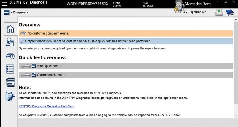
It’s crucial to connect a battery maintainer to the vehicle and ensure the scan tool is powered. XENTRY Diagnostics Kit 3 presents different menus based on the vehicle year. Newer models (typically 2008 onwards) often feature auto-detect VIN and variant selection. The XENTRY main diagnostic menu typically includes six key cells:
- Home Screen: Displays notes, quick test options, and current quick test status. Customer complaint selection becomes available after initiating a quick test.
- Components Fitted: Represented by a stethoscope and notepad icon, this cell lists all components installed in the vehicle.
- Customer Complaint Screen: Indicated by a car icon with an exclamation mark. XENTRY requires a quick test before accessing this screen.
- Control Unit View: A bullet point tab providing a list of all control units in the vehicle.
- CAN Network Tree: Depicted as a diagnostic tree, this crucial tab visualizes all CAN networks, aiding in identifying communication issues and offline components.
- Special Functions: Illustrated by manuals and a wrench icon, this section offers functions like stored control unit logs, retrofit entries, and system information.
Initiate a quick test, and XENTRY will prompt you to start the diagnostic scan. This process polls all modules, performing a “health check” to confirm online status. “No communication” indications for specific modules flag areas requiring further investigation. The quick test provides a valuable overview of network health and communication faults. Printing the test results is beneficial for record-keeping and verification. A visual inspection under the hood and vehicle can sometimes reveal obvious issues like damage or tampering that correlate with the symptoms.
Post-quick test, each module is marked with a green check (OK), “F” (Fail), or “I” (Information). Multiple codes across modules are common at this stage, many potentially unrelated to the current issue. Re-focus on the customer’s primary complaint. Prioritize diagnosing faults most likely connected to that specific issue. While stored codes might be historical, informing the customer of potential additional issues is prudent. Select control units and fault codes relevant to the problem. Opening individual fault codes reveals detailed information, including freeze-frame data, fault occurrence details (current or intermittent status), and often a “tests” tab.
Resist the immediate urge to clear codes unless confident of a hard fault. Retaining fault memory allows access to guided tests within XENTRY, crucial for pinpointing intermittent issues. The “tests” tab, available for individual faults, offers XENTRY-guided procedures. These tests often involve voltage checks at specific pins, oscilloscope waveform analysis (e.g., crank position sensor), and bi-directional controls to assess component functionality. Follow each test command; XENTRY provides potential causes, probable causes, or indicates if the fault is not currently present.
XENTRY seamlessly integrates with WIS/ASRA, TIPS, wiring diagrams, and connector assignments, accessible within the diagnostic flow. A clear understanding of the customer complaint, combined with TSBs and knowledge of similar vehicle histories, significantly improves diagnostic accuracy.
Leveraging XENTRY Measurement Technology HMS 990 USB for Advanced Diagnostics
The XENTRY system offers optional расширение with the HMS 990 Measurement Technology USB, significantly enhancing diagnostic capabilities. This tool, working in conjunction with XENTRY Diagnostics Kit 3, provides technicians with extensive electrical system measurement options. The HMS 990 enables a wide array of checks, from basic voltages and resistances to complex ignition and dwell angles, and even comprehensive alternator testing. Its integrated multimeter allows for precise measurement of voltage, current, resistance, frequency, temperature, and pressure, essential for thorough electrical system analysis.
Furthermore, the Xentry Measurement Technology Hms 990 Usb facilitates in-depth combustion analysis by cylinder. It monitors compression and rotational speed, immediately alerting technicians to deviations from specified values. This capability is invaluable for diagnosing engine performance issues and identifying mechanical problems impacting electrical systems.
The HMS 990 USB also incorporates a universal oscilloscope and a 12-channel oscilloscope, critical for analyzing signal integrity. Technicians can measure signals from sensors like crankshaft and camshaft position sensors, visualizing waveforms to identify signal distortions or anomalies. Long-term signal recording is possible, enabling capture of intermittent faults. Saved measurements can be recalled for later analysis and comparison, streamlining complex diagnostics.
While a standalone lab scope and multimeter can perform similar measurements, the HMS 990 USB integrates these tools seamlessly within the XENTRY environment. This integration provides convenience and guided testing procedures, making diagnostics more efficient and less prone to errors. The test sequences within XENTRY often directly prompt for lab scope measurements, and the HMS 990 is ideally suited to fulfill these requirements, providing a cohesive and streamlined diagnostic workflow.
Key Features of HMS 990 USB:
- Integrated Multimeter: Accurate measurement of voltage, current, resistance, frequency, temperature, and pressure.
- 12-Channel Oscilloscope: Simultaneous signal analysis from multiple sources, ideal for complex system diagnostics.
- Combustion Analysis: Cylinder-specific analysis of combustion duration, compression, and rotational speed.
- Long-Term Recording: Capture and storage of measurements for intermittent fault analysis.
- Seamless XENTRY Integration: Guided testing and data interpretation within the XENTRY diagnostic environment.
Benefits of Using HMS 990 in Diagnostics:
- Enhanced Accuracy: Precise measurements for reliable diagnostics.
- Improved Efficiency: Streamlined workflow with integrated tools and guided tests.
- Comprehensive Analysis: Wide range of measurement capabilities for diverse diagnostic needs.
- Faster Troubleshooting: Pinpoint faults quickly with advanced measurement and analysis features.
- Reduced Diagnostic Time: Integrated tools and guided processes minimize manual setup and interpretation.
Other Essential Tools for CAN Bus Diagnostics
Beyond XENTRY and the HMS 990, other specialized tools are valuable for CAN bus diagnostics. A DLC connector breakout box is particularly useful for isolating communication issues. When fault codes indicate a bus problem connected to the Diagnostic Link Connector (DLC), a breakout box allows for direct resistance testing at the DLC. A healthy CAN bus should measure approximately 60 ohms resistance across the CAN high and CAN low lines due to the parallel termination resistors (typically 120 ohms each). Incorrect resistance readings signal a problem requiring further isolation of bus nodes. This is where the CAN bus tree diagram in XENTRY becomes invaluable.
A lab scope is also essential for analyzing CAN bus signal integrity. By observing data packets, technicians can identify signal distortions, noise, or interference indicative of controller issues. Voltage measurements are equally important. A voltage drop to zero suggests a ground fault in the line or a connected module, while voltage readings near 5V or 12V may indicate a short to power.
For vehicles equipped with MOST networks, a MOST loop tool is indispensable. Diagnosing MOST networks, being optical, doesn’t involve voltage measurements. A MOST loop tool bypasses suspected components in the MOST ring. By unplugging a module and inserting the loop, communication restoration indicates the bypassed module as the fault. This tool is crucial for efficient MOST network troubleshooting.
General Guidelines for CAN Bus Diagnostics
Several general guidelines are crucial for safe and effective CAN bus diagnostics:
- Fused Jumpers: Always use fused jumper wires when bridging connections to prevent accidental shorts and damage.
- Component Testing After Replacement: After replacing any component, perform a component test in XENTRY to ensure proper function, connection integrity, and correct coding.
- Fault Code Interpretation: Be aware that XENTRY-guided test sequences may generate additional fault codes. These are often test-induced and should be disregarded, focusing on the original fault codes. Maintaining a record of initial fault codes is essential.
- Controlled Fault Introduction: Only induce counter faults (short circuits or open circuits) if explicitly instructed by the XENTRY diagnostic tree. Unnecessary fault introduction can complicate diagnostics and potentially damage components.
By adopting a structured diagnostic approach, leveraging the capabilities of XENTRY Diagnostics Kit 3 and xentry measurement technology hms 990 usb, and utilizing essential tools like breakout boxes and MOST loop tools, automotive technicians can confidently and efficiently diagnose even complex CAN bus issues. A clear strategy, vehicle system understanding, and methodical use of diagnostic information provided by XENTRY are key to stress-free and accurate CAN bus diagnostics.