Maintaining your Mercedes-Benz Sprinter van often involves understanding its electrical system, and a crucial part of that is the fuse box. Fuses protect your vehicle’s circuits from overloads, preventing damage to sensitive components. If you’re experiencing electrical issues in your second-generation Mercedes Sprinter (W906, NCV3), produced between 2006 and 2018, knowing the Mercedes Sprinter Fuse Box Diagram is essential for effective troubleshooting and repair.
This article serves as your expert guide to navigating the fuse boxes in your Mercedes Sprinter. We provide detailed fuse box diagrams for models from 2006, 2007, 2008, 2009, 2010, 2011, 2012, 2013, 2014, 2015, 2016, 2017, and 2018. You’ll learn the locations of the fuse panels within your van and understand the function of each fuse and relay, empowering you to diagnose and resolve electrical problems efficiently.
For instance, locating the cigar lighter fuses in your Mercedes-Benz Sprinter is a common need. These are actually spread across multiple fuse boxes. You’ll find fuses #13 (Cigarette lighter, PND power socket) and #25 (12V socket – center console) in the Instrument panel fuse box. Additionally, the Fuse Box under the driver’s seat houses fuses #23 (12V left rear socket, load/rear compartment), #24 (12V socket under driver’s seat base), and #25 (12V right rear socket, load/rear compartment). Understanding these locations is the first step to resolving power outlet issues.
Instrument Panel Fuse Box (Main Fuse Box)
The primary fuse box in your Mercedes Sprinter, often referred to as the main fuse box, is the Instrument Panel Fuse Box.
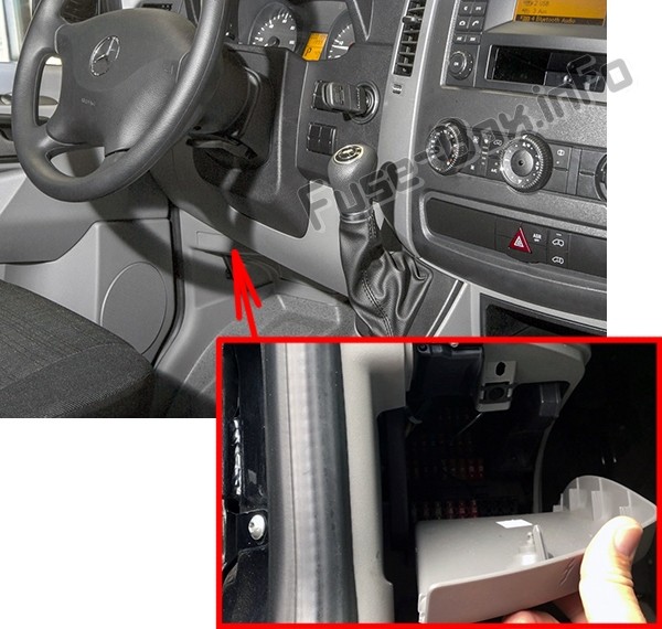
Instrument Panel Fuse Box Location
The Instrument Panel Fuse Box is conveniently located inside the cabin, on the driver’s side. To access it, you’ll need to locate and remove the cover situated beneath the instrument panel.
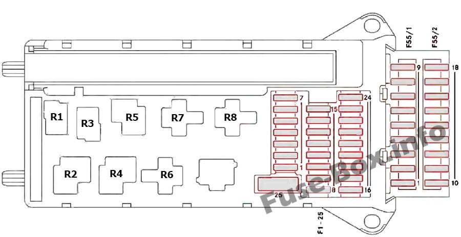
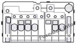
Instrument Panel Fuse Box Diagram
Once you’ve located and opened the Instrument Panel Fuse Box, you’ll see a layout similar to the diagram below. This Mercedes Sprinter fuse diagram details the position and function of each fuse and relay within this panel.
Instrument Panel Fuse and Relay Assignment
| # | Consumer | Amp |
|---|---|---|
| 1 | Horn | 15 |
| 2 | ESTL (electric steering lock) ignition lock | 25 |
| 3 | Terminal 30 Z, vehicles with a gasoline engine/ ignition lock/instrument cluster | 10 |
| 4 | Light switch/switch unit on center console | 5 |
| 5 | Windshield wipers | 30 |
| 6 | Fuel pump Terminal 87 (5) (Vehicles with code MI6/MH3/XM0) | 15/10 |
| 7 | MRM (jacket tube module) | 5 |
| 8 | Terminal 87 (2) | 20 |
| 9 | Terminal 87 (1) / Terminal 87 (3), vehicles with a gasoline engine / Terminal 87 (3), vehicles with a diesel engine | 25/20/25 |
| 10 | Terminal 87 (4) | 10 |
| 11 | Terminal 15 R vehicle | 15 |
| 12 | Air bag control unit | 10 |
| 13 | Cigarette lighter/glove box lamp/radio/body manufacturer loading tailgate/PND (personal navigation device) power socket | 15 |
| 14 | Diagnostics connection/light switch/instrument cluster/deactivating reverse warning device/anti-theft protection with vehicle tracking | 5 |
| 15 | Headlamp range control/front-compartment heating | 5 |
| 16 | Terminal 87 (1) / Terminal 87 (3) (Vehicles with code MI6/MH3/XM0) | 10 |
| 17 | Air bag control unit | 10 |
| 18 | Terminal 15 vehicle/ brake light switch | 7.5 |
| 19 | Interior lighting | 7.5 |
| 20 | Front-passenger door power window switch/ terminal 30/2 SAM (signal acquisition and actuation module) | 25 |
| 21 | Engine control unit | 5 |
| 22 | Brake system (ABS) | 5 |
| 23 | Starter motor Terminal 87 (6) (Vehicles with code MI6/MH3/XM0) | 20/10 |
| 24 | Diesel engine, engine components/control unit, vehicles with a natural gas engine NGT (Natural Gas Technology) | 10 |
| 25 | 12 V socket (center console) for tire sealant | 25 |
| Fuse block F55/1 | ||
| 1 | Driver’s door control unit | 25 |
| 2 | Diagnostics connection | 10 |
| 3 | Brake system (valves) | 25 |
| 4 | Brake system (delivery pump) | 40 |
| 5 | Terminal 87 (2a) engine M272, OM651 / Terminal 87 (2a) engine OM642, OM651 (NAFTA) | 7.5 |
| 6 | Terminal 87 (1a) engine OM6426 (Vehicles with code XM0) / Terminal 87 (1a) engine OM651 (Vehicles with code XM0) / Terminal 87 (3a) engine M272, M271, OM651 | 10/7.5/7.5 |
| 7 | Headlamp cleaning system | 30 |
| 8 | Anti-theft alarm system (ATA)/beacon/beacon with siren | 15 |
| 9 | Additional turn signal module | 10 |
| Fuse block F55/2 | ||
| 10 | Radio 1 DIN / Radio 2 DIN | 15/20 |
| 11 | Mobile phone/tachograph/additional recorder (Latin America only) /navigation cradle (Vehicles with code XM0) | 7.5 |
| 12 | Front blower/auxiliary heating blower setting (Vehicles with code MI6/MH3/XM0) | 30 |
| 13 | Auxiliary heating system digital timer/radio receiver/DIN slot basic wiring/FleetBoard/antitheft protection with vehicle tracking | 7.5 |
| 14 | Seat heating | 30 |
| 15 | Brake system control unit | 5 |
| 16 | Heating, rear compartment heating/ front-compartment air conditioning | 10 |
| 17 | Convenience lighting / Motion detector / Reading and cargo compartment lamp (courier vehicles) / Cargo compartment lighting | 10/7.5/10/7.5 |
| 18 | Rear-compartment air-conditioning system | 7.5 |
| Relays | ||
| R1 | Horn relay | |
| R2 | Windshield wiper setting 1/2 relay | |
| R3 | Fuel pump relay (Not on vehicles with code MI6/MH3/XM0) / Starter relay, terminal 15 (Vehicles with code MI6/MH3/XM0) | |
| R4 | Windshield wipers on/off relay | |
| R5 | Starter relay, terminal 50 | |
| R6 | Relay, terminal 15 R (normally open contact) | |
| R7 | Engine control unit relay, terminal 87 | |
| R8 | Relay, terminal 15 (reinforced relay) |

Fuse Box Under Driver’s Seat
The second crucial fuse panel is located under the driver’s seat of your Mercedes Sprinter. This box houses fuses and relays for various systems, particularly those related to the vehicle’s rear and specialized functions.
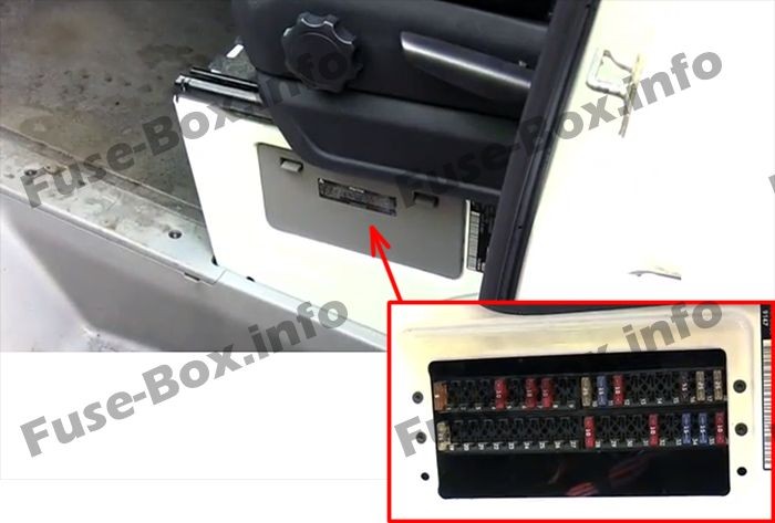
Fuse Box Under Driver’s Seat Location
Accessing the fuse box under the driver’s seat requires locating the panel cover, usually on the seat base itself, and removing it to expose the fuses and relays.
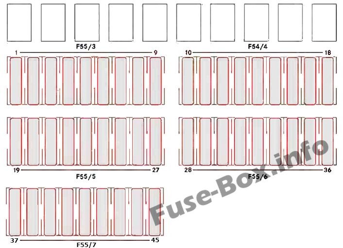
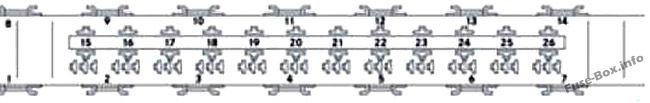
Fuse Box Under Driver’s Seat Diagram
Below is the fuse box diagram Mercedes Sprinter for the panel under the driver’s seat. This diagram outlines the specific fuses and relays within this location and their respective functions.
Fuse and Relay Assignment – Fuse Box Under Driver’s Seat
| # | Consumer | Amp |
|---|---|---|
| Fuse block F55/3 | ||
| 1 | Mirror setting/rear window defroster | 5 |
| 2 | Rear window wiper | 30 |
| 3 | Auxiliary heating, digital timer/rear view camera/neutral gate switch, starting-off aid and allwheel drive/engine runon/DIN slot basic wiring (roof)/FleetBoard/anti-theft protection with vehicle tracking/emergency hammer lighting in the rear compartment | 5 |
| 4 | Tachograph/ADR working speed governor/ power take-off/AAG (trailer control unit) | 7.5 |
| 5 | ECO Start/control unit EGS (electronic gearbox control) | 5/10 |
| 6 | All-wheel drive control unit / Auxiliary oil pump | 5/10 |
| 7 | ESM (electronic selector module) | 10 |
| 8 | Loading tailgate/tipper vehicle PARKTRONIC (Vehicles with code XM0) | 10 |
| 9 | Rear compartment air conditioning, compressor clutch, disengageable reverse warning device | 7.5 |
| Fuse block F55/4 | ||
| 10 | Terminal 30, body/ equipment manufacturer | 25 |
| 11 | Terminal 15, body/ equipment manufacturer | 15 |
| 12 | D+, body/equipment manufacturer | 10 |
| 13 | Fuel pump FSCM (Fuel Sensing Control Module) / Fuel pump relay (Vehicles with code MI6/MH3/XM0) (NAFTA) | 20/15 |
| 14 | Trailer power socket | 20 |
| 15 | Trailer recognition unit | 25 |
| 16 | Tire pressure monitor PARKTRONIC (Pre-facelift vehicle) | 7.5 |
| 17 | Programmable special module (PSM) | 25 |
| 18 | Programmable special module (PSM) | 25 |
| Fuse block F55/5 | ||
| 19 | Overhead control panel without ATA (Anti-Theft Alarm system) and without rain sensor / Overhead control panel with ATA (Anti-Theft Alarm system) / Overhead control panel with rain sensor | 5/25/25 |
| 20 | License plate lamp (courier vehicles)/perimeter lamp (NAFTA)/identification lighting (NAFTA) | 7.5 |
| 21 | Terminal 30, body electrics (courier vehicles) / Rear window defroster without ATA (Anti-Theft Alarm system) / Rear window defroster with ATA (Anti-Theft Alarm system) | 15/30/15 |
| 22 | Rear window defroster 2 / Vehicle socket (courier vehicles) | 15/20 |
| 23 | 12 V left rear socket, load/rear compartment / Electric system: non-MB body | 15/10 |
| 24 | 12 V socket under the base of driver’s seat | 15 |
| 25 | 12 V right rear socket, load/rear compartment | 15 |
| 26 | Hot-water auxiliary heating | 25 |
| 27 | Electrical heater booster (PTC) / Auxiliary warm-air heater | 25/20 |
| Fuse block F55/6 | ||
| 28 | SRB starter relay (fuse and relay module) (NAFTA) (Vehicles with code XM0) / Starterfor electrical supply support using the additional battery | 25 |
| 29 | Terminal 87 (7), gas system, vehicles with a natural gas engine (NGT) (Natural Gas Technology) / Selective Catalytic Reduction control unit, vehicles with exhaust gas aftertreatment (NAFTA) / Terminal 30, all-wheel drive, control unit | 7.5/10/30 |
| 30 | Auxiliary heat exchanger fan / Brake booster (NAFTA) | 15/30 |
| 31 | Rear compartment heating blower / Sliding door closing assistance, left / Electric sliding door, left | 30/15/30 |
| 32 | Selective Catalytic Reduction relay supply, vehicles with exhaust gas aftertreatment / KEYLESS ENTRY | 5/10 |
| 33 | Electric sliding door, right / Sliding door closing assistance, right / ENR (level control) control unit / Compressor air suspension | 30/15/30/30 |
| 34 | Selective Catalytic Reduction heater 3 DEF (Diesel Exhaust Fluid) supply reservoir, vehicles with exhaust gas aftertreatment, 6 cyl. Diesel (Vehicles with code MH3) (NAFTA) / Selective Catalytic Reduction heater 1 DEF, vehicles with exhaust gas aftertreatment diesel (Not for vehicles with code MH3) | 15/20 |
| 35 | Selective Catalytic Reduction heater 2 hose, vehicles with exhaust gas aftertreatment, 6 cyl. Diesel (Vehicles with code MH3) (NAFTA) / Selective Catalytic Reduction heater 2 DEF, vehicles with exhaust gas aftertreatment diesel (Not for vehicles with code MH3) | 15/25 |
| 36 | Selective Catalytic Reduction heater 1 delivery pump, vehicles with exhaust gas aftertreatment, 6 cyl. Diesel (Vehicles with code MH3) (NAFTA) / Selective Catalytic Reduction heater control 3 DEF, vehicles with exhaust gas aftertreatment diesel (Not for vehicles with code MH3) | 10/15 |
| Fuse block F55/7 | ||
| 37 | COLLISION PREVENTION ASSIST/FCW (Forward Collision Warning) / Blind Spot Assist/BSM (Blind Spot Monitor) | 5/5 |
| 38 | Multifunction camera with Highbeam Assist / With a warning when leaving a lane | 10/10 |
| 39 | Body electrics (courier vehicles) / Rear-compartment air-conditioning system / Roof ventilator / Siren | 7.5/7.5/15/15 |
| 40 | Auxiliary battery charge current (Vehicles with auxiliary battery) | 15 |
| 41 | SAM (signal acquisition and actuation module) auxiliary battery reference voltage (Vehicles with auxiliary battery) | 7.5 |
| 42 | Rear-compartment air-conditioning system | 30 |
| 43 | Electrical step/sliding door, right | 10 |
| 44 | Electrical step/sliding door, left | 10 |
| 45 | Electrical step, control system and warning buzzer | 5 |
Pre-Fuse Boxes
In addition to the main fuse boxes, Mercedes Sprinter vans also utilize pre-fuse boxes. These high-current fuse boxes are typically located closer to the battery and protect major electrical components.
Pre-Fuse Box in Battery Compartment
One pre-fuse box is situated in the battery compartment, located in the footwell on the left-hand side of the vehicle (driver’s side in many regions). This Mercedes Sprinter pre fuse box location is critical for protecting high-amperage circuits.
Pre-Fuse Box Diagram – Battery Compartment (F59)
| # | Consumer | Amp |
|---|---|---|
| 1 | Preglow relay / Secondary air pump for vehicles with a gasoline engine | 80/40 |
| 2 | Air-conditioning system coolingfan – cab without partition and without rear-compartment air-conditioning system / Air-conditioning system cooling fan – cab with partition and reinforced without rear-compartment air-conditioning system / Air-conditioning system cooling fan – cab/ Electrical suction fan / Starter relay, terminal 15 (Vehicles with code XM0) / Starter relay unsupported (Vehicles with code XM0) | 60/40/40/25/25 |
| 3 | SAM (signal acquisition and actuation module)/SRB (fuse and relay module) | 80 |
| 4 | Auxiliary battery/ retarder / Rear-compartment air-conditioning system | 150/80 |
| 5 | Terminal 30 pre-fuse boxes, SAM (signal acquisition and actuation module)/SRB (fuse and relay module) / Terminal 30 electrical heater booster (PTC) input (Vehicles with code XM0) | 150/Bridge |
| 6 | Connection point on the base of the seat / Pre-fuse box in the base of the seat (Vehicles with code XM0) | Bridge/Bridge |
| 7 | Rear-compartment air-conditioning system / Electrical heater booster PTC | 80/150 |
Pre-Fuse Box at the Base of the Driver’s Seat (Auxiliary Battery)
For Sprinter models equipped with an auxiliary battery, an additional pre-fuse box is located at the base of the driver’s seat. This Mercedes Sprinter auxiliary battery fuse box manages the high-current circuits for the auxiliary battery system.
Pre-Fuse Box Diagram – Driver’s Seat Base (Auxiliary Battery) F59/7
| # | Consumer | Amp |
|---|---|---|
| 1 | Unassigned | – |
| 2 | SAM (signal acquisition and actuation module)/SRB (fuse and relay module) | 80 |
| 3 | Unassigned | – |
| 4 | Auxiliary battery input | 150 |
| 5 | Connection point on the base of the seat / Pre-fuse box at the base of the seat | Bridge |
| 6 | SAM (signal acquisition and actuation module)/SRB (fuse and relay module), terminal 30 fuse box | 150 |
| 7 | Additional battery input / Connection for socket fuse on vehicles with additional battery | Bridge |
| 8 | Retarder in combination with battery cutoff relay | 100 |
| 9 | Additional battery | 150 |
| 10 | Snowplow hydraulic pump / Loading tailgate / Tipper | 250 |
Pre-Fuse Box Diagram – Driver’s Seat Base (Auxiliary Battery) F59/8
| # | Consumer | Amp |
|---|---|---|
| 11 | Terminal 30 starter battery input | Bridge |
| 12 | Unassigned | – |
| 13 | Electrical heater booster (PTC) / Rear-compartment air-conditioning system | 150/80 |
| 14 | Air-conditioning system coolingfan – cab without partition and without rear-compartment air-conditioning system / Air-conditioning system cooling fan – cab with partition and reinforced without rear-compartment air-conditioning system / Air-conditioning system cooling fan – cab open vehicle model designation / Electrical suction fan | 60/40/40/70 |
| 15 | Unassigned | – |
| 16 | Retarder not in combination with battery cutoff relay / Battery cutoff relay | 100/150 |
| 17 | Unassigned | – |
| 18 | Alternator | 300 |
Relays in the Seat Base of the Left Front Seat
Located within the seat base of the left front seat, you’ll find a collection of relays that control various functions in your Mercedes Sprinter. Understanding this Sprinter relay diagram is crucial for diagnosing relay-related electrical issues.
Relay Assignment – Seat Base of the Left Front Seat
| # | Relays | Description |
|---|---|---|
| R1 | K6 | Starter relay, right-hand drive (Vehicles with code XM0) |
| R2 | K41 | Load relief relay, terminal 15 |
| R3 | K41/5 | Starter relay, terminal 15 |
| R4 | K64 / K110 | Secondary air injection/secondary air pump relay / SCR relay, vehicles with exhaust gas aftertreatment (Selective Catalytic Reduction) |
| R5 | K27 | Fuel pump relay |
| R6 | K23/1 | Blower relay, front, blower setting 1 |
| R7 | K41/2 | Load relief relay, terminal 15 R |
| R8 | K6/1 / K6 | Starter relay, additional battery / Starter relay, left-hand drive (Vehicles with code XM0) |
| R9 | K13/5 | Rear window defroster relay 1 |
| R10 | K13/6 / K51/15 | Rear window defroster relay 2 with ATA (Anti-Theft Alarm system) / Snow plow relay, low-beam headlamps, left |
| R11 | K117/3 / K51/16 | Electrical step relay 1, left / Snow plow relay, low-beam headlamps, right |
| R12 | K117/4 / K51/17 | Electrical step relay 2, left / Snow plow relay, high-beam headlamps, left |
| R13 | K41/3 / K51/18 | Load relief relay, terminal 15 (2) / Snow plow relay, high-beam headlamps, right |
| R14 | K13/7 | Windshield heating relay 1 |
| R15 | K88 | Body manufacturer relay, terminal 15 |
| R16 | K88/1 | Body manufacturer relay, terminal 61 (D+) |
| R17 | K95 / K93 | Loading tailgate basic wiring relay / Comfort illumination relay |
| R18 | K2 | Headlamp cleaning system relay |
| R19 | K51/10 | Beacon with siren relay |
| R20 | K39/3 | ATA (anti-theft alarm system) relay, horn |
| R21 | K108 / K116 / K23/2 | Perimeter/identification lighting relay (NAFTA) / License plate lamp relay (courier vehicles) / Blower relay, hot-air auxiliary heating, blower setting 1 |
| R22 | K23/3 | Blower relay, hot-air auxiliary heating, blower setting 2 |
| R23 | K39/1 / K124/1 | Siren relay / Terminal 61 (D+) relay, anti-theft protection with vehicle tracking |
| R24 | K117/1 | Electrical step relay 1, right |
| R25 | K117/2 | Electrical step relay 2, right |
| R26 | K121 / K124 | Reverse warning device off relay / Anti-theft protection with vehicle tracking relay |
Other Relays
| Relay | Description |
|---|---|
| K57 | Battery cutoff relay, left-hand-drive vehicle |
| K57/4 | Battery cutoff relay, right-hand-drive vehicle |
| K9 | Air-conditioning system relay, auxiliary fan (duo) |
| K9/2 | Air-conditioning system relay, auxiliary fan (mono) |
| K9/5 | Rear-compartment air conditioning relay, auxiliary fan |
| K120 | Auxiliary battery relay (Vehicles with auxiliary battery) |
Further Resources for Fuse and Electrical System Maintenance:
- How to check the fuses? – Learn the proper techniques for inspecting fuses in your Sprinter.
- How to replace a blown fuse? – Step-by-step instructions for safely replacing a faulty fuse.
- Why do car fuses blow? – Understand the common causes of blown fuses to prevent future issues.
- Types of automotive fuses – Familiarize yourself with the different types of fuses used in automotive applications.
By utilizing this comprehensive guide to the Mercedes Sprinter fuse box diagram, you’ll be better equipped to diagnose and address electrical issues in your van, ensuring its continued reliable operation. Remember to always consult your vehicle’s owner’s manual for the most accurate and model-specific information.