The High Pressure Fuel Pump (HP Pump) in modern Mercedes-Benz engines is a sophisticated component, crucial for delivering the precise fuel pressure required for efficient combustion. While waiting for my low-pressure fuel pump tester kit to be serviced, let’s delve into the intricacies of the HP pump, a Bosch unit, and how to diagnose it using Xentry, focusing on understanding the Fuel Quantity Control Valve (QCV) actuation angle.
This HP pump isn’t primarily about volume delivery; its core function is pressure boosting. It acts as a pressure multiplier, meaning its liter-per-minute output is inherently limited by the Low Pressure Fuel Pump (LPFP). Simply put, it cannot output more fuel than it receives from the LPFP.
For a clear visual explanation of its operation, this video animation provides excellent insight:
Our HP pump belongs to this family from Bosch Motorsport, although our specific model likely has a slightly lower fuel pumping capacity: https://www.bosch-motorsport.com/con…113098763.html. The linked document indicates a capacity of 1.1 cm3 or 1 milliliter/cc per camshaft rotation – representing the maximum pumping stroke volume when the piston reaches Top Dead Center (TDC) and Bottom Dead Center (BDC).
Audi tech also provides valuable information on similar HP pumps, starting from the 16:00 mark in this video:
Camshaft Lobes and Pumping Events
The M276 3.5L engine utilizes 3 fuel lobes to drive this pump, whereas my 3.0L engine employs 4. This difference in lobe count can influence pressure and pressure stability per engine revolution, depending on the “lift” of the lobes. In our 4-stroke engines, the camshaft rotates at half the speed of the crankshaft. Therefore, at an engine speed of 5,000 RPM, the camshaft RPM is 2,500.
Let’s examine the pumping events based on lobe count:
- 3 fuel lobes: 3 lobes x 2,500 RPM camshaft = 7,500 pumping events per minute
- 4 fuel lobes: 4 lobes x 2,500 RPM camshaft = 10,000 pumping events per minute
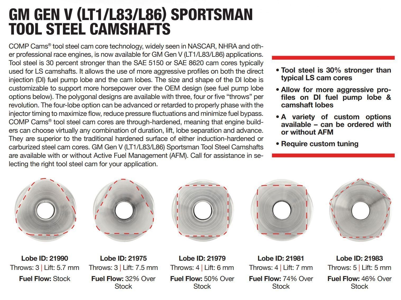
Here are examples of camshaft fuel lobes for the M276 3.5L engine:
And for the 3.0 TT camshaft:
The M278 engine also utilizes 4 lobes and, notably, employs two HP pumps.
Fuel Quantity Valve and Pressure Control
The HP fuel pump incorporates a Fuel Quantity Valve/Solenoid, which is designed to be normally-open. In the event of engine computer failure or a faulty Quantity Control Valve, it will remain open. This default open state allows a “limp home mode” by utilizing the low-pressure fuel pump pressure of 4-5 BAR to supply the injectors, enabling basic engine operation. This is a crucial safety feature, although not ideal for performance.
While the basic concept seems straightforward, the precise control required for activating the Quantity Control Valve is complex.
Let’s visualize the camshaft lobe’s highest protrusion/lift as TDC (Top Dead Center) and its lowest point as BDC (Bottom Dead Center) for understanding the pumping cycle.
Due to the check valve design, the HP pump generates pressure only when the Quantity Control Valve (QCV) is energized or CLOSED at the correct moment during the pump’s compression stroke. Conversely, suction volume is achieved when the QCV is un-energized, allowing fuel intake during the pump’s downward or suction stroke. Crucially, suction volume can be reduced if the QCV is energized/closed even during the suction stroke. Remember, the Fuel Quantity Valve/Solenoid is normally-open.
Here’s a simplified estimation of the pumping cycle in an ideal scenario:
Xentry Diagnostics and Actuation Angle Frustration
So, where does the diagnostic challenge arise, particularly when using Xentry? It centers around the “Actuation Angle of Quantity Control Valve” parameter observed in Xentry/scanner diagnostics. This parameter can be perplexing.
My engine, with its 4 fuel lobe camshaft, completes one pumping cycle (suction + discharge) every 90 degrees of camshaft revolution. This breaks down to approximately 45 degrees for suction and 45 degrees for pressurization. In contrast, a 3.5L engine with 3 fuel lobes completes a cycle every 120 degrees, resulting in roughly 60 degrees for suction and 60 degrees for pressurization.
Theoretically, the optimal “Actuation Angle of Quantity Control Valve” for maximum pressure/output in my pump should be around 45 degrees after BDC towards TDC.
This video provides a relevant demonstration around the 00:30 mark:
According to my Xentry data, at a 33.5° Actuation Angle of Quantity Control Valve (let’s call it ANGLE for simplicity), I achieve a fuel pressure of 191.9 BAR. This seems logical, as 33.5° out of a potential 45° represents approximately 74.4% of the working angle being utilized.
However, the puzzle deepens when examining another data point: at a 66.6° ANGLE, the fuel pressure drops to 150.4 BAR. This is counterintuitive, as typically, GDI engines exhibit their highest fuel pressure at higher engine RPMs.
Considering a 65° ANGLE (rounding from 66.6° for easier calculation), the deviation from the ideal 45° is 20 degrees (65° – 45° = 20°). This 20-degree difference might be intentionally limiting the fuel pump’s pressure output below its potential 200 BAR capability. My assumption is that this 20-degree difference represents a period during the SUCTION phase that is deliberately not being fully utilized, while the full 45-degree compression phase is still occurring.
Given that my engine’s estimated maximum fuel consumption rate is only 1.93 liters per minute, and the HP pump’s theoretical output at 4,000 engine RPM is significantly higher at 6.4 liters per minute (in a perfect scenario, before efficiency losses), I hypothesize that the engine computer strategically reduces fuel supply at higher RPMs. This could be achieved by intentionally shortening the suction period by those 20 degrees through QCV control, balancing volumetric flow and pressure.
This leads to several key questions:
- Is my engine designed for a 150 BAR GDI pressure system, or is it closer to a 200 BAR system as I initially believed?
- Why is the system not utilizing the potential for a higher 191 BAR pressure, which could enhance fuel atomization, especially at higher engine RPMs, opting instead for 150 BAR?
- Could there be a timing issue with my HP Pump fuel quantity valve?
Investigating further, can I use an oscilloscope to analyze the camshaft angle in relation to the activation duration of the Fuel Quantity Valve? Yes, I can. However, the challenge lies in determining the precise TDC position of the camshaft lobes, which is needed as a zero-degree reference point. One TDC point would suffice.
Is the “TOTAL Actuation Angle of Quantity Control Valve” reported by MB Xentry referring to camshaft angle or crankshaft angle? Camshaft angle seems more logical in this context. Let’s proceed with that assumption.
At idle in my garage, Xentry reports a 30.9-degree actuation angle.
My oscilloscope measurements indicate a 40-camshaft-degree energization duration for the QCV. Is this entire 40° duration within the suction period? Without knowing the exact TDC position, it’s difficult to say definitively.
Below is an oscilloscope capture showing 4 QCV activation periods per camshaft revolution. For this capture, I intentionally used a 360-degree scale to represent one camshaft revolution, simplifying degree-based analysis for camshaft timing. For camshaft-to-crankshaft correlation checks, a 720-degree scale would be necessary.
Based on Bosch HP Pump patents, that brief PWM signal visible on the right side of my measurement (around the 290 ms mark) might be a noise reduction feature for the piston, akin to electromagnetic braking. For those interested in further headache, here is the patent document:
The crucial question remains: where are the four TDC points on my camshaft? I don’t know with absolute precision. Any estimation would likely be off by 10-15 degrees.
Further investigation is needed to pinpoint the TDC and fully understand the QCV actuation and its impact on fuel pressure. This analysis is crucial for diagnosing potential fuel delivery issues and ensuring optimal engine performance, and is a key aspect of using Xentry for advanced Mercedes-Benz diagnostics, including potentially relating to injector performance indirectly through fuel pressure regulation.
To be continued…